Goto USPTO Information Page for this patent
Henry Richard's 3/25/1902 (improved frog)
#696,081
imiTED STATES PATENT OFFICE. |
||
| To all whom it may concern: Be it known that I, LEONARD BAILEY, of Wilichester, in the county of Middlesex and State of Massachusetts, have invented a new 5 and useful Improvement in Hand-Planes; and I do hereby declare that the same is fully described and represented in the fol- lowing specification and the accompanying drawings, of which— 10 Figure I denotes a top view of a smooth- ing plane having my invention applied to it; Fig. 2, a side elevation of it, while Fig. 3 is a central, vertical and longitudinal section of it. Fig. 4 is an underside view of the 15 plane iron and its cap, Fig. 5 being a top view of the same. Fig. 6 is a view of the clamp lever and thumb cam thereof to be hereinafter described. The object of my invention is to provide 20 the plane with a ready means of fixing the plane iron or cutter in the stock or of re- moving the same therefrom as well as of adjusting the plane iron in the stock as cir- cumstances may require. 25 In the drawings, A, exhibits the plane stock furnished with a throat, B, for the reception of the cutter or plane-iron, C, or the same and its cap iron, D. In the above mentioned drawings the cap iron, D, is ex- 30 hibited as confined to the plane iron or cut- ter, G, by means of a screw A, extending up- ward from the underside of the cutter G, and through a long slot, &, formed in the said cutter as shown in Figs. 3 and 4. The 35 bearing surface of the throat or that marked d, d, in Fig. 3, is furnished with a recess, e, for the reception of the head of the screw, h, by which the cap iron is confined to the plane iron, such recess being made of a suf- 40 ficient size or diameter to allow the neces- sary longitudinal movements of the plane iron. Furthermore, the cap-iron as shown in the drawing, is made with a hole, /, ar- ranged midway between its two edges and 45 directly over the slot in the plane iron, such hole being to enable the plane iron and its cap to be passed over the head of a bearer • or screw F, inserted in the plane stock and. made to project from the bearing surface 50 cl, cl, as shown in Fig. 3. In connection with this screw or bearer, F, a clamp lever or plafe, G-, is employed, it being formed as represented in the drawings and hinged or jointed at its upper end to a thumb cam, H. 55 -Moreover, the clamp lever, G, has an elon- gated slot, s, made through it, the said slot |
in one half its length being circular in form and having a diameter or width somewhat larger than the head of the bearer or screw, F, while the remainder of the slot is con- 60 striicted of a width or diameter less than that of the head of the screw and sufficient to receive the shank of the screw the whole being as shown in the drawings. In con- sequence of the slot being so made we are 66 enabled to slip or pass the clamp lever, Gr, over the head of the screw and to press the said clamp lever, (r, downward in such man- ner as to cause the head of the bearer or screw to project beyond the sides of the slot, 70 and constitute a fulcrum for the clamp plate when the thumb cam is turned down into the position as shown in Figs. I and 2. By turning the thumb cam down, we clamp or confine the plane iron in the stock, but by 75 turning such thumb cam upward so as to bring it into the position as represented in Fig. 7 (which is another longitudinal sec- tion of the plane) we loosen the clamp lever from the bearer in such manner as to enable 80 us either to remove it therefrom or to adjust the plane iron as circumstances may require. By turning backward the thumb cam, it will be made to so operate against the plane iron or the cap thereon as to raise the upper end 85 of the clamp lever and force the lower end against the bearer in such manner as to cause the lower end of the clamp plate to be pressed downward upon the pla-ne iron and secure such iron firmly upon its bearing 90 surface, d, d. Thus it will be seen that by means of the bearer, the clamp lever and the thumb cam the plane iron may be se- cured in place in the throat of the plane stock or released therefrom with great fa- 95 cility or expedition. By making the shank of the bearer to screw into the stock we cause the bearer to be adjustable with reference to the seat of the plane iron, and therefore we have a 100 means of readily adapting the bearer to a plane iron of any ordinary thickness, whether provided or not with a cap iron, the adjustment of the bearer being for the pur- pose of causing the thumb cam and the 105 clamp lever to be brought into the proper situations to enable them by their conjoint action as described to fasten the plane iron to the stock. If desirable, there may be two bearers, F, but I prefer to have but one, as BaO such is quite sufficient. These bearers may be arranged near the edges and may project | |
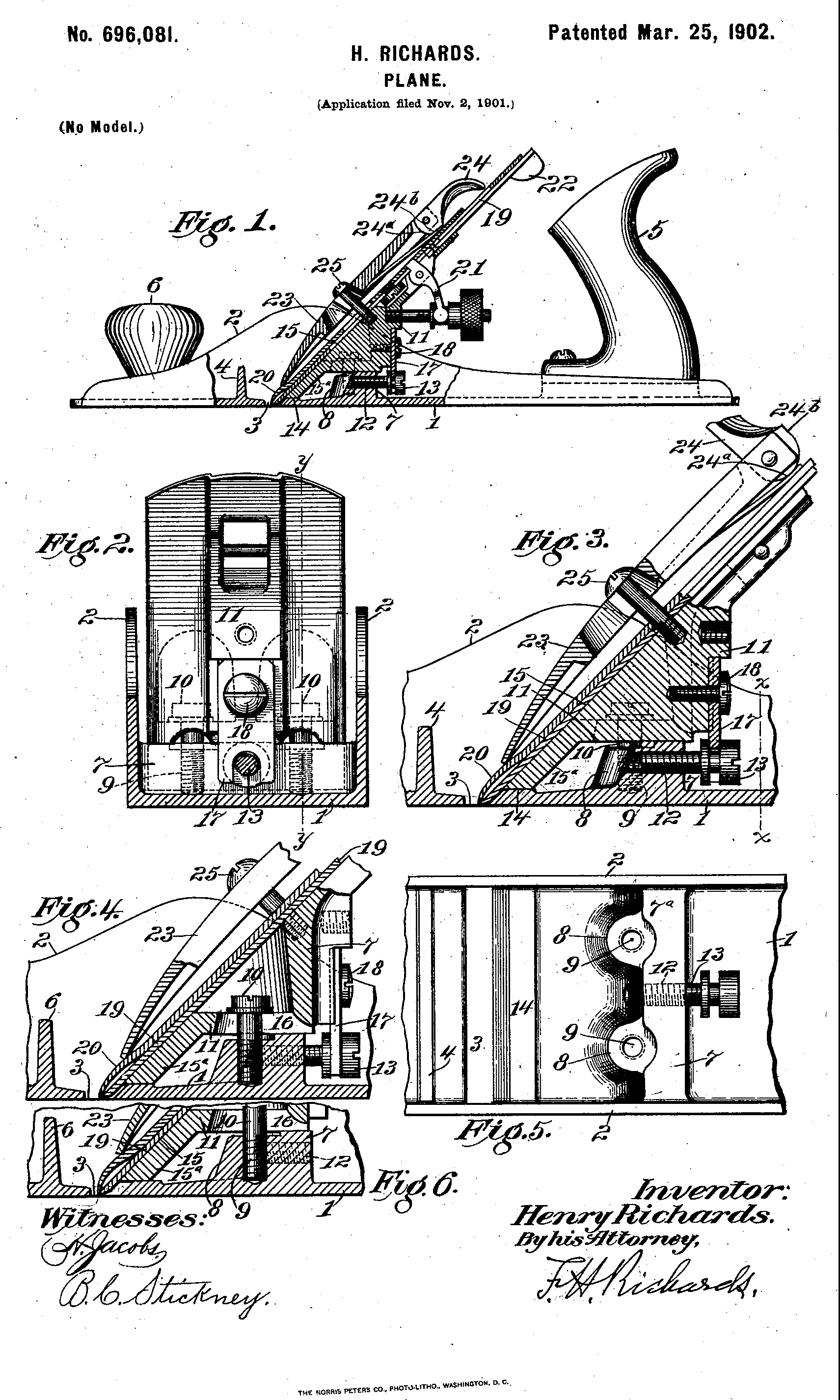
| of the plane, due to the springing of the frog, by either the downward drag or the upward resistance of the wood. In general I furnish a construction adapted to meet all of the nu- g merous and peculiar requirements necessary in practice for satisfactory results in planes of this class, and especially when employed upon highly-resistant woods and when set for the production of fine surfaces, in which cases io any flexibility or chattering is particularly objectionable. A further object of my invention is to over- come a fault in the cam usually employed to clamp the plane-irons upon the frog, where- •tg by the pressure at the lower portion of the blade is relieved and chips are permitted to crowd up between the blade and the cap-plate thereon. In tlie drawings accompanying and form- 20 ing part of this specification, Figure I is a side elevation, partly in section/of a plane made in accordance with my improvements. Fig. 2 is a cross-section taken on the line x x of Fig. 3 and showing an adjustable frog 23 from the rear. Fig. 3 is an enlarged sectional elevation of the frog and parts adjacent there- to shown at Fig. I, this section being taken on the median line of the plane. Fig. 4 is a section similar to Fig. 3, but taken on the 30 line y y of Fig. 2. Fig. 5 is a plan of the middle section of my improved plane-stock and showing also a frog-adjusting screw. Fig. C is a fragmentary view similar to Fig. 4, but showing the frog as adjusted forwardly 35 so as to nearly close the throaty In the several views similar parts are des- ignated bysimilar numerals of reference. The plane-stock may consist of a thin floor or sole I, finished upon its bottom surface, 40 and thin side flanges 2, connected forwardly of the throat 3 by means of a thin high stiff- ening-rib 4. The stock may also be provided with the usual backhandle 5 and front knob 6. At a point well in rear of the throat I join 45 the flanges 2 by a high rib 7, which may be rather thin in cross-section, and trusses the side flanges, producing a stiff box-like de- vice. The top edge of the rib is faced off at 'i" in parallelism with the bottom or working •)o surface of the stock. Upon the forward side of the rib 7 I provide bosses 8, one at each side of the median line of the plane, in which I form threaded vertical holes 9 for the re- ception of screws 10, which clamp a frog II 35 upon the stock. At a point between the bosses 8 I form in the rib 7 a threaded hori- zontal perforation 12 for the reception of a screw 13, whereby the frog may be adjusted forward and back, so as to close or open the 5o throat 3. Along the rear edge of the throat I thicken the sole and finish its upper surface at 14 in parallelism with the top 7'-' of the rib 7, so that the surfaces 14 and 7" may coop- erate to form a chair for the frog. The thick- 63 ened portion at 14 braces the comparatively weak sole of the plane at this point, but is |
:, I very much depressed below the surface I", I i so that said surfaces form steps, which are ti separated, so as to give a broad bearing for - the frog. 7� v The frog consists of the body portion II g and a forwai'dly-sloping bed 15, the lower i part of the. latter at Ijs projecting downwardly r and forwardly from the body portion. At .s its lower edge said projecting part is fitted 75 y upon the step 14, so that the frog may be ad- justed forward and back in parallelism with •- the working face of the plane and be always o firmly seated upon the chair. As will be ob- )- served at Fig. 4, the frog is provided with So e slots 16 for the binding-screws 10, permitting 0 the adjustment of the frog, which may be e effected by means of the fore-and-aft screw 13, whose grooved head engages a slotted ear i- 17, secured to the frog by a screw 18. 85 a A blade 19 lies upon the bed 15 and pro- e jects beyond the lower edge thereof into the i. throat 3. This blade may be of the usual x construction and is provided with a customary 3: cap-plate 20. The nsnal longitudinal and 90 d transverse adjustments may be effected by )- means of a screw-operated yoke-lever 21 and n a swinging lever 22. The plate-irons 19 and . a 20 are releasably secured upon the bed by e means of a clamping-bow 23, which bears at 95 e its lower end upon the cap-plate 20 and at its k upper end is provided with an improved cam- '. lever 24 and works upon the head of a screw ;. 25, projecting from tlie frog. y It will be observed that by dividing the ioo chair into two well-separated portions abroad ,- seat is obtained for the frog without unduly weighting the plane. The forward step 14 r steadies the frog, and hence the blade, at a ', pointcloseattheworkingsurfaceoftheplane, 105 y the plane being adjustable for different kinds �- of work without detracting from the steadi- d ness of the frog at this point. The high truss b 7 renders the stock especially rigid at the n very point where the distortive stresses are no e produced by the clainping-screws, so that the e frog may bo securely clamped upon its broad )- chair without warping the thin plane-stock. ,t The feature of adequately supporting the g fore part of the frog when it is adjusted for- 115 e wardly for different classes of work, as at Fig. h 6, is of great importance in my improved h plane, since the blade is always given a firm �- bearing at a point very close to its cutting 1 edge. My improvement is of great value 120 e when the plane is used upon highly-resistant i- woods and when set for the production of fine a surfaces, in which case any flexibility of the d knife is particularly objectionable, producing e chattering and making it difficult or impossi- 125 .fc ble to produce the desired finish. Tfc will also e be seen that by dividing the chair into two b steps and placing one thereof close to the edge )- of the throat, so as to afford a positive sup- :- port for the lower edge of the frog, I am able 130 y to heighten the rear step materially, and I ~ +T-I ��- yi ,c,,l IT rv\ o ~-~\�i~ o 11 IT cf+\ fFriln tit l\ tTrtiTn T\1 n nn- | |
| stock, bu.t apply the stiffeninff-tnoss at the very portion which is subjected to the most stress. Moreover, I am enabled to increase the depth of the holes for the clamping-screws s and also to make ample provision for a fore- and-aft adjusting-screw and all without add- ing materially to the weight, but instead re- ducing the objectionable thickness of metal usual in stock of this kind. io A further and important feature of my im- provements appertains to the means illus- trated for putting the fore part or nose of the frog normally under tension, whereby I am enabled to secure a perfect action of the 15 plane.. As will be observed at Fig. 4, the clamping-screws 10 bear upon the frog at a point between the two steps of the chair, thereby not only clamping the bodyofthe frog securelyupontherearstep, butalsotend- zo ing to flex the fore part of the frog and hold- ing it down upon the seat 14 with consider- able pressure. Owing to this normal tension upon the frog, it results that applying pres- sure to or removing it from the blade when 25 planing operates in a far less degree than heretofore to spring the frog. It will be un- derstood that when a frog is held upon a broad single seat by means of screws located in the usual manner this normal stress or 30 tension of the frog is wanting, and tho fore part of the frog consequently is left some- what flexible, so that the pressure of the wood upward under the point of the blade springs up both the blade and the frog and permits 35 a vibration which in many cases amounts to a chattering of the edge of the blade upon the wood. Thus it will be seen that I not only provide a positive support at all.times for the fore part of the frog, but also that I spring 40 said fore part upon said support, so that the blade is prevented from chattering either by the downward pull or by the upward thrust of the wood. lthuswiden-the range of work for which this type of plane is adapted and 45 secure a more reliable operation and better results generally on all kinds of work. ; Owing to the proximity of the clamping- sorews to the rear-step. 7" and their remote- ness from the forward step 14, the pressure 50 upon the frog is distributed between the two steps in substantial correspondence to the relativeabilitiesofthe two portions of the thin stock to sustain the pressure without warping or distortion, so that the frog is thus $5 put into condition to avoid chattering with- out incurring aliability of distorting the stock. The cam-lever 24 is formed with a curved workingsurface24", which as the lever is 6o turned gradually forces the bow against the plane-irons, said surface .24� terminating in atangential stop-surface 24*, which 'arrests the lever just as the point of greatest com- pression is reached, so that there is nO possi- 65 bilityofareactionalmovemenfcof theplane- irons, as is usually the case, and the lattel |
he proviag.theiv action and avoiding theliabil- )st ity of chips working between the irons. ,se ~Sob the .least of the several valtiable tea- 70 ws tnres of my invention consists in the provi- •e- sion for adjustment of the frog forth and back .d- in substantial parallelism with the finished :'e- bottom or working surface of the stock and :'al at the same time enabling said frog however 75 adjusted to be firmly supported not only at in- its main or body portion, but also at its front is- end. At least- one and preferably both of he the elements 15* and 14 are finished in sub- im stantial parallelism with the working surface So he of the stock, and the same is true of the ele- he ments 7 and II. In the construction illus- a trated a parallelism of adjustment is secured ir, through a parallelism of bearing-surfaces he with the working or bottom face of the stock, 85 .d- one of said parallel bearing-surfaces being in id- front and being formed or provided upon 3r- either the frog or the stock, and another, of on said parallel hearing-surfaces being in rear 3s- and also formed or provided upon either the <)o en frog or the stock, the surfaces contacting with an said parallel bearing-surfaces being them- ,n- selves preferably also parallel with said work- a ing face of the stock, thereby giving consid- ed erable breadth or area of Contact at both-the 95 or fore and aft portions of the frog, which is de- ire sirable. It willbeunderstoodthatby having- ie- at least one such parallel bearing-surface in od front and at the lower portion of.the plane and gs at least one more such parallel bearing-snr- ico its face in rear and at a considerable elevation- it 3 a becomes practicable both to adjust the frog he forth and back and also to support the same tly firmly both fore and aft at all such adjust- he ments. I consider it of especial value that 105 ng the portion 7 of the stock has a stepwise ar- he rangement relatively to the bearing-surface by at the throat in said stock, since thereby it ist becomes practicable in this class of planes to irk effect a parallel adjustment of the frog while iio nd always firmly supporting not only the body her but also the fore foot of the latter, this fore , foot being an exceedingly sensitive part of ig- the plane and the true action thereof being te- of the utmost importance. It will be ob- 115 ire served that the frog at its forward end affords wo a direct support for the -lower ends of-the ;he plane-irons and also at said end and close to Jhe the lower ends of said plane-irons bears di- )nt reetly upon the sole of the stock at all times. 120 ins By-maintaining the frog constantly at the th- same vertical distance from the working sur- Jhe face or floor of the stock the throat may be . closed or opened to any extent by a simple ied and rapid manipulation without the neces- 125 is sity of resetting the plane-irons either in lon- lhe gitudinal direction or transversely bymeans ' in of the. lever 22, while at all times the action ;sts of the plane is rendered most satisfactory. iin- III this instance the adjustment of the frog 130 3si- is effected by means of a fore-and-aft screw ne- threaded into the material of the stock be- ter neath the base of the frog and connected to IITI- -hi-i~ la tm� | |
| Variations may be resorted to within the scope of my invention) ana portions of my im- provements may be used without others. Having described my invention, I claim— g 1. A metallic plane-stock having a thin sole and thin side flanges, and also having at the rear edge of the throat a depressed step, and well in rear thereof an elevated step; the up- per surfaces of said steps being finished par- io allel with each other and substantially par- allel with the working surface of the stock, so as to form a chair for a frog; and said ele- vated step being in the form of a high rib erected upon the sole and trussing the side ig flanges, so as to form a box-like device. 2. A metallic plane-stock having a thin sole and thin side flanges, and also having at the rear edge of the throat a depressed step, and well in rear thereof an elevated step; said de- 20 pressed step being in the form of a slight thickening of the edge of the sole along the rear side of the throat, and said elevated step being in the form of a high rib erected upon the sole and trussing the side flanges, 25 so as to form a box-like device; the upper surfaces of said steps being finished parallel with each other and substantially parallel with the working surface of the stock, so as to form a chair for a frog. 30 3. A metallic plane-stock having a high step which is provided with a deep threaded hole for receiving a frog-clamping screw; said stock also having at the rear edge of the throat and forward of said high step a depressed step; 35 and said steps being finished in parallelism with the working surface of the stock and co- operatively adapted to form a chair for a frog. 4. A metallic plane-stock having a thin sole and thin side flanges, and also having well in 40 rear of the throat a thin high transverse rib which trusses said flanges and also forms a rear step, said rib being provided with two deep holes for receiving frog-clamping de- vices, one hole at each side of the stock; said 45 stock also having at the rear edge of the throat a depressed forward step which is formed by thickening the throat edge of the sole; said step being cooperatively adapted to form a chair for a frog, and each thereof being fin- 50 ished parallel with the working surface of the stock. 5. A metallic plane-stock having a. rear step provided at its front side with a threaded hole for receiving a frog-clamping screw; and also 55 having at the rear edge of the throat and for- ward of said threaded hole a depressed step; said steps being finished in parallelism with the working surface of the stock and coop- eratively adapted to form a chair for a frog. 6o C. A metallic plane-stock having a sole and side flanges and also having well in rear of the throat a narrow high transverse rib which trusses the flanges and also forms a rear step; said step having at its forward side two thread- 65 ed holes, one at each side of the median line of the stock, for receiving frog-clamping am'nws: said sola also havins" at thn roar fid""fi | e of the throat, a thickening which forms a de- i- pressed forward step; said steps being fin- ished in parallelism and cooperatively adapt- 70 - ed to form a chair for a-frog. e 7. A metallic plane-stock having a sole and e side flanges, and also having well in rear of d the throat a narrow high transverse rib which i- trussessaidflangesandalsoformsarearstep; 75 •- said rib having a fore-and-aft threaded per- •- f oration for receiving a long frog-adjusting :, screw, which may project forwardly through )- said rib; and also having an np-and-down b threaded hole for receiving a frog-clamping So e screw; said stock also having at the rear edge of the throat a depressed forward step; said e steps being cooperatively adapted to form a e chair for a frog, and being finished parallel d with the working surface of the stock. , 85 '- 8. A metallic plane-stock having a sole and .t side flanges and also having well in rear of e the throat a narrow high transverse rib which d trusses said flanges and also forms a rear step; d said rib having a fore-and-aft threaded per- 90 ',, foration for receiving a long frog-adjusting ir screw, which may project forwardly through si said rib; andsaidsolealsohavingattherear )l edge of the throat a depressed forward step; s said steps being finished in parallelism and qc being substantially parallel with the working p surface of the stock, and being cooperatively e adapted to form a chair for a frog. a. 9. A metallic plane-stock having a sole and it side flanges and also having well in rear of ioo i; the throat a narrow high transverse rib which n trusses said flanges and also forms a rear step; )- said rib having a fore-and-aft threaded per- f. foration for receiving a frog-adjusting screw, e and also having at its front side two vertical 105 n threaded holes, one upon each side of said b perforation, for receiving frog - clamping a screws; said sole being also thickened at the o rear edge of the throat so as to form a de- ?- pressed forward step; said steps being fin- iio d ished in parallelism and substantially paral- it lei with the working surface of the stock, and y being cooperatively adapted to form a chair d for a frog. a 10. Ametallic plane-stock having well in 115 i- rear of the throat a pair of vertically bored e and threaded bosses formed upon the front side of a rear step; said stock also having at p the rear edge of said throat and forward of e said bosses a thickening which forms a dc- 120 \o pressed forward step; and said steps being r- finished in parallelism with the working sur- >; face of the stock and cooperatively adapted h to form a chair for a frog. )- II. Ametallicplaue-stockhavingasoleand 125 P side flanges and also having well in rear of d the throat a pair of vertically-bored bosses )f formed upon the front side of a narrow high h transverse rib that trusses said flanges, and also forms a rear step; said stock also having at the rear of said throat a depressed forward step; said steps being cooperatively adapted to form a chair for a frog; and said rib being | |
| and-aft threaded perforation for receiving a frog-adjusting device. 12. In a plane, the combination of a stock and a frog; the stock having a thin sole and s thin side flanges, and also having at the rear edgeoffchethroatadepressedstep,andwellin rear thereof an elevated step; the apper sur- faces of said steps being finished parallel with each other and substantially parallel with the io working surface of the stock; said elevated step being in the form of a high rib erected upon the sole and trussing the side flanges, so as to form a box-like device; and said frog being fitted to and adjustably secured upon 15 said steps. 13. In a plane, the combination of a stock and a frog; the stock having a sole and side flanges, and also having well in rear of the throat a narrow high transverse rib which 20 trusses said flanges and also forms a rear step; said stock also having at the rear edge of the throat .a depressed forward step; and said frog being fitted upon said steps and secured thereto by one or more screws which pass zg down into deep holes formed in said truss, and being also connected to a fore-and-aft screw which engages a threaded perforation also formed in said truss. 14. In a plane, the combination with a stock 30 having a chair consisting of separated seats, of a frog fastened upon said chair by means of a device which bears upon the frog at a point between said seats and thereby causes the frog to bear upon both seats. 35 15. In aplane, the combination with a stock having a chair consisting of separated seats, of a frog fastened upon said chair by means of a device which bears upon the frog a.t a point between said seats but close to one there- to of, so as to cause the frog to bear unequally upon the seats. 16. In a plane,the combination with a stock, • of a frog fastened thereon and capable of fore-and-aft adjngtment; said stock having a 45 sole and side flanges, and having at the rear edge of the throat a depressed step,.and well in rear of the throat a narrow high transverse rib which trusses said flanges and also forms a rear step; and said: frog being fastened by s& one or more screws placed at the forward side of said rear step, and bearing upon the frog between its fore-and-aft supports, so that the frog is rigidly seated upon the rear step and is also caused to bear firmly upon the front 55 step at all such adjustments of said frog. 17. In a plane, the combination of a stock and a frog; the stock having a thin sole and thin side flanges, and also having at the rear edge of the throat a depressed step, and well 60 in rear thereof an elevated step; the upper surfaces of said steps being finished parallel with each other and substantially parallel with the working surface of the stock; said elevated step being in the form of a high rib 65 erected upon the sole and trussing the side flanges, so as to form a box-like device; and _.— J-3 J.-- —~ I-_ •---~ CCC^~&127; 1. L -T ~ • J 1-� | ?a cured upon said steps; plane-irons; a clamp- ing-bow; and a cam - lever formed with a ck curved working surface 24", which as the ie- 70 nd ver is turned gradually forces the t)ow against ar the plane-irons, said surface '2i�• terminating in in a tangentialstop-surface 24", which arrests ir- the lever Just as the point of greatest com- th pression is reached. 75 he 18. In a plane, the combination of a stock ed and a frog; said stock having at the rear bor- ed der of the throat a depressed step, and said 3S, frog having a foot bearing upon said step; og at least one of said step and foot elements 8o on being finished in substantial parallelism with the working surface of the stock and also en- ck gaging with and guiding the other thereof; •-ie said stock also having well in rear of said he throat an elevated step, and said frog also 85 ch having a base adapted to rest upon said ele- P; vated. step; and at least one of said elevated- he gtep and frog-base elements being also finished •id in parallelism with the workingsurface of said ed stocbandengagingwithandguidingtheother c)c -ss thereof; whereby said frog may be adjusted is, forth and back in substantial parallelism lft with the said working surface, so as to close on and open the throat, andbealwaysconjointly supported by said steps. 95 ok 19. in a plane, the combination of a stock :s, and a frog; said stock having at the rear hor- ns der of the throat a depressed step, and said a frog having a foot bearing upon said step; at es least one of said step and foot elements be- ioo ing finished in substantial parallelism with ek the surface of the plane and also engaging ts, with and guiding the other thereof; said stock ns also having well in rear of said.throat an ele- a vated step, and said frog also having a base 105 'e- adapted to rest upon said elevated step; and ly at least one of said elevated-step and frog- base elements being also finished in parallel- ik, ism with the working surface of said stock of and engaging with and guiding the other no ?a thereof; whereby said frog may be adjusted ar forth and back insubstantial parallelism with in the said working surface so as to close and •se' open the throat, and be always conjointly as supported by said steps; a fore-and-aft screw 115 ?y threaded into the material of said stock be- de neath the base of said frog; and a connection og between said frog and said screw; whereby he said frog may be adjusted forth and back. id 20. In a plane, the combination of a stock 120 nt and a frog; said stock havingatthe rear bor- der of the throat a depressed step, and said ck frog having a foot bearing upon said step; at ad least one of said step and foot elements be- ar ing finished in substantial parallelism with 125 911 the surface of the plane and also engaging 'er with and guiding the other thereof ;saidstock lei also having well in rear of said throat an ele- lel vated step, and said frog also having a base -id adapted to rest upon said elevated step; at 130 •ib least one of said elevated-step and frog-base de elements being also finished in parallelism nd with tha 'wm•k\n{' srirfan.ft of sairl stof.lrand ina with the working sariace oi saia stocK ana se- ! enga.a;mg with and gnidingthe other thereof; | |
| whereby said. frog may be adjusted forth an back in substantial parallelism with the sai working surface, so as to close and open th throat, and still be firmly supported upon sai s steps conjointly; and a screw threaded, dow into the material of said elevated step, an effective to ciainp said frog to said stock at a adjustments of the former. 21. In a plane, the combination of a stoc io and.a frog; said stock having at the rear edg of the throat a depressed step, and said fro having a foot bearing upon said step; at lea' one of said step and foot elements being fir ished in substantial parallelism with the sni 15 face of the plane and also engaging with an guiding the other thereof; said stock ala having well iu rear of said throat an el( vated step) and said frog also having a has adapted to rest upon said elevated step; a 20 least one of said elevated - step and fro: base elements being also finished in pai-alle ism with the working surface of said stoc and engaging with and guiding the othe thereof; whereby said frog may be adjuste zg forth and back in substantial parallelism wit the said working face so as to close and ope the throat, and. always be supported by sai steps; a fore-and-aft screw threaded into th material of said stock beneath the base c 30 said frog; a connection between saidfrogan said screw whereby said frog may be adjust cd forth and back; and a screw threaded dow into the material of said step and effective t clamp said frog to said stock at all adjust 35 ments of the former. 22. A metal plane-stock having athin sol and thin side flanges and also having a hig rib erected upon the sole and trussing the sid flanges, so as to form a box-like device we 40 in rear of the throat; said stock being als provided forwardly of said rib with a d( pressed step, and having also a rear elevate hearing-surface having a stepwise relation t said depressed step and which conjointly wit 45 said. depressed step forms a chair in comb nation with a frog formed to engage and b guided by the parallel surfaces of said steps whereby it may be adjusted forth and. bac said steps being finished iu substantial pai | nd. allelism with the working surface of said ' lid. stock. .he 23. In a plane, the combination with a stock, lid of a frog thereon adjustable fore and aft in wii parallelism with the working surface of said nd stock; and plane-irons carried by said frog; ; all said frog at its forward end both affording a direct support for the lower ends of the plane- ick irons, and also at said forward end and close lge to the lower ends of said plane-irons bearing •og upon the sole of the stock at all positions to < ast which said frog may be adjusted; and sepa- in- rate means for supporting the main portion ur- or body of said frog in. such a manner as to nd permit said adjustment thereof; said sepa- Iso rate supporting means being engaged by said < ile- frog at a material elevation above the sole of ise said stock. at 24. In a plane, the combination with a stock, 3g- of a frog bearing upon the sole of the plane el- at the rear border of the throat; an elevated ; ick support well in rear of the throat; said frog ier having a main seat resting upon said elevated ;ed support; means for clamping said frog; a ith fore-and-aft screw threaded into said sup- ien port beneath said frog; and an ear provided ', lid upon said frog and connected to said screw, .he whereby the frog may be adjusted by turn- of ing said screw; said frog, at all such adjust- nd ments thereof, bearing at its front end upon st- the sole at the rear border of the throat, i wn 25. In a plane, the combination of a stock to and a frog clamped thereon; a main support st- for said frog being provided upon said stock and rising to a material elevation above the ale sole thereof; andafore-and-aftscrew thread- i gh ed into said main support beneath said frog Lde and connected to the latter so as to effect ell fore-aud-aft adjustments thereof; said frog Iso having a part which extends forwardly and 3e- downwardly from said support and bears at ( .ed its lower end upon the sole of the stock at the to rear border of the throat, at all adjustments screw. 1. Witnesses: H. S. WALTEE | |