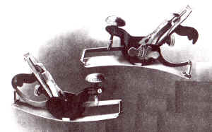
Stanley No. 113 Circular Plane
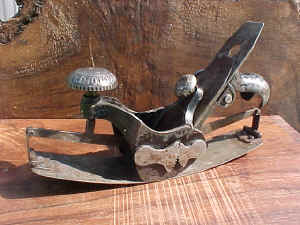
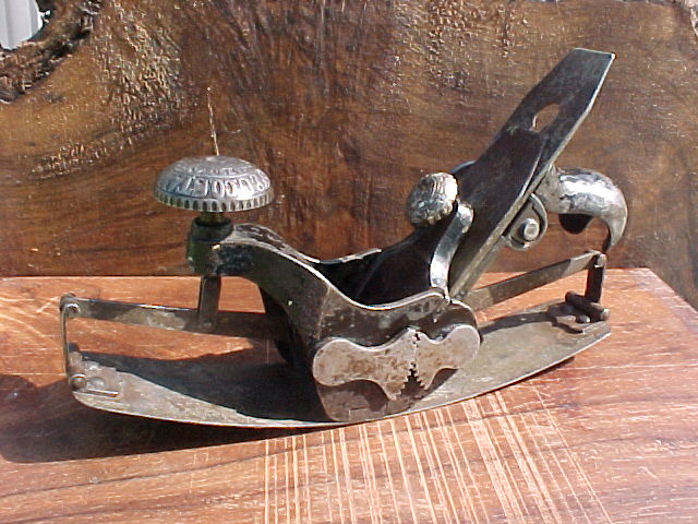
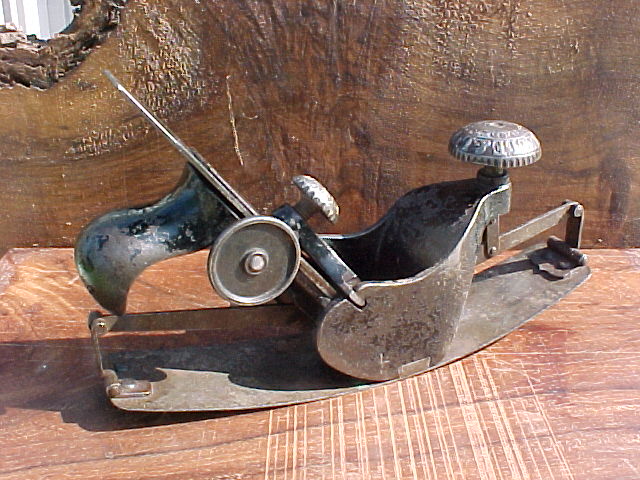
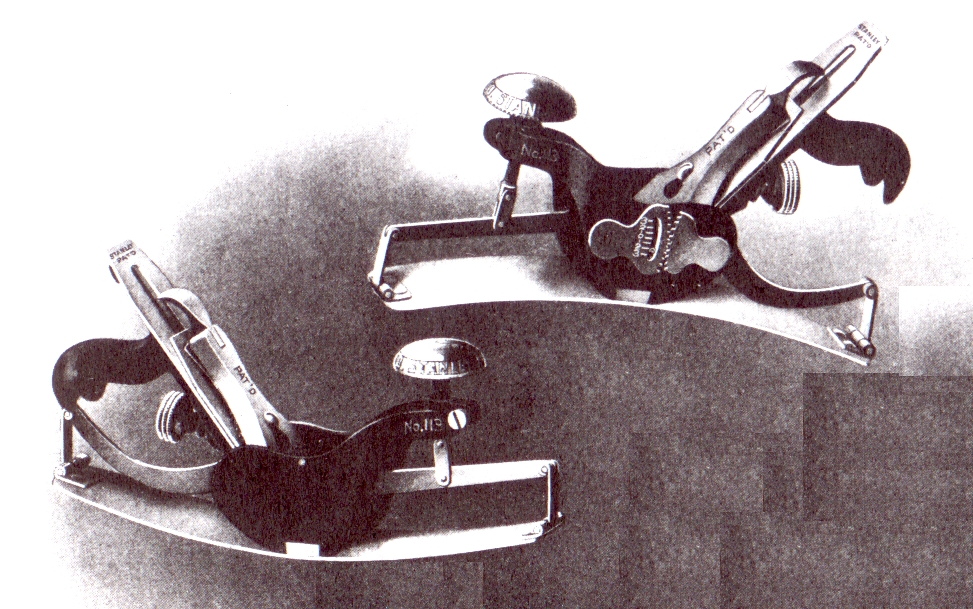
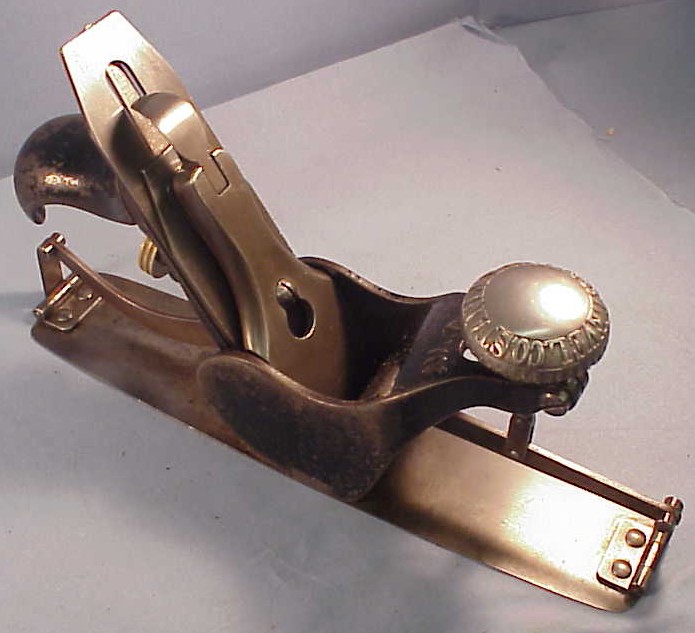
Stanley #113 Circular Plane (Type 1, 1877-1880)5
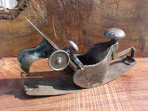
Stanley #113 Circular Plane (Type 1, 1877-1880)5
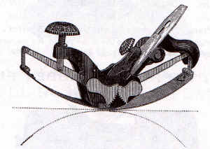
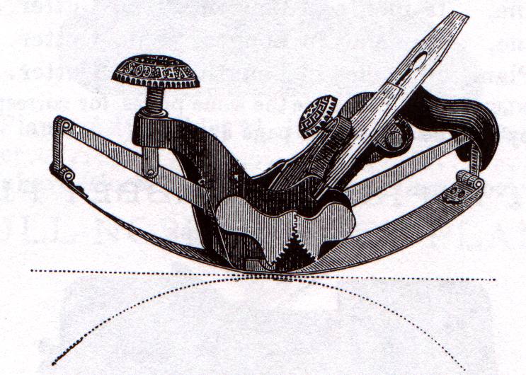
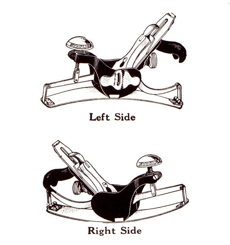
1879 Catalog Image of Stanley #113 (Type 1, 1877-1880)2
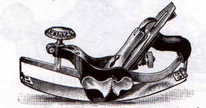
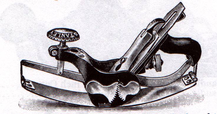
1898 Catalog Image of Stanley #113 (Type 4 and later)1
1909 Catalog Image of Stanley #113 Showing Graduated Scale Added To Interlocking Gears

1923 Catalog Image of Stanley #113
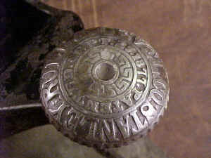
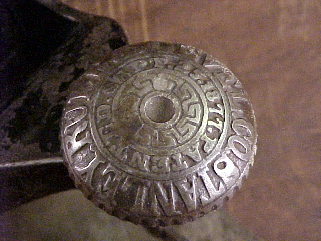
Stanley #113 Type 1 Front Knob with 9/25/1877 Patent Date and Center Maze Design.2
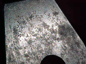
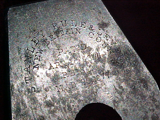
Stanley #113 Blade Type 1 Style Trademark with April 18,1876 and March 20,1877 Patent
Dates5
 Sargent's
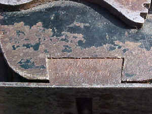
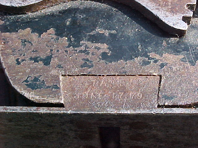
6/17/1879 Patent Date on Dovetailed Sole Connection of Stanley #113 Type 1Circular
Plane5
Sargent's
6/17/1879 Patent Date on Dovetailed Sole Connection of Stanley #113 Type 1Circular
Plane5
Manufactured1: 1877 to 1942
Patents1: Henry Clark's 9/25/1877 (basic design), Traut & Richard's 3/20/1877 (cap alignment), Sargent's 6/17/1879 (sole attachment), Josef Nicht's 2/8/1876 (lateral), Justus A.Traut's 10/21/1884 (improved lateral), Justus A.Traut's 7/24/1888 (disc pivot lateral), Alix Stanley & E. A. Schade's 9/8/1903 (graduated side gear) , Earl V. Higbee's 7/18/1933 (lever cap)
Dimensions1:10 inch's long; 10-1/4 inches long in 1936 and later
Cutter1: 1-3/4 inch wide
Construction1: Cast iron
Finish1: Japanned, nickel plated trimmings
User Info1: For planing concave and convex surfaces as in circular frames and in serpentine drawer fronts. care must be taken when planing that this plane is kept straight and is not skewed as is customary when using a smooth plane. The flexible sole adjusts by turing the large front knob. The adjustment linkage in the #113 has a tendency to strip out and the arms holding the sole are thin strips of steel and did not hold up under heavy use. The rear handle also had a tendency to break if under heavy strain or if dropped. Some users perfer the #113 over the #20 due to the fact that it would give or flex a little on the rear half of the sole and is more suitable for working radii that are not perfectly symmertrical.
Average Price1: $85 to $150 (includes all types not individually listed)
Type 8a1: $150 to $350 (1936 to 1939)
Type 41: $75 to $175 (1900 to 1906)
Type 31: $100 to $200 (1892 to 1899)
Type 21: $125 to $250 (1880 to 1891)
Type 11: $150 to $450 (1877 to 1880)
General Notes for the #113 Circular Plane1
Type 1 - (1877 to 1880) Has an ornate front knob with "Stanley Rule Level
Co." and "Patented September 25,1877 in a circular border. The cutter is stamped
"Stanley Rule & Level Co., New Britain, CT" and "Pat'd April
18,1876" and "Reis'd Mar. 20, 1877." Screw down lever cap with fancy cap
screw. The cutter has a special two-piece screw to join it with the cap iron. This special
screw fits into a cutter adjustment with two apertures. The cutter adjustment wheel on the
side of the plane is solid and has a japanned finish. The two small pieces of steel that
are hinged and riveted to the front and back of the flexbile sole are pointed toward the
center of the plane resembling the shape of a shield. Sargent's 6/17/1879 patent date is
stamped on the dovetailed lug attaching the sole to the body of the plane.
Type 2 - (1880 to 1891) Front knob identical to Type 1 except part of the
decorative "maze" design is removed from the center of the knob. Cutter screws
are now standard; cutter markings are the same as Type 1. Cutter adjustment now has one
aperature. The cutter wheel on side of plane now has a four-hole design in the casting and
is nickel plated. Two small pieces of steel on the sole no longer have the decorative
point shape (shield) but are rectangular. Some models observed with Type 1 parts, but not
the Type 1 cutter and frog.
Type 3 - (1892 to 1899) Has Schade's 4/19/1892 patent cutter. Patent
dates removed from front adjustment knob.
Type 4 - (1900 to 1906) furnished with modern type frog, lateral
adjustment and Bailey style lever cap. Sargent's 6/17/1879 patent date removed from
dovetailed lug.
Type 4a - (1903) has graduated scale added to interlocking gears on the
side of the plane. These gears controled symmetrical movement of the front and back of the
sole.
Type 5 - (1907 to 1910) has "T" TM on cutter.
Type 6 - (1910 to 1920) has "V" TM on cutter.
Type 7 - (1921 to 1935) Either Sweetheart or "AA" TM on cutter.
Type 8 - (1936 to 1942) Has "BB" notched TM on cutter.
Type 8a - (1936 to 1939) has decorative design on large sole adjustment
screw.
Type 9 - (1940 to 1942) has a plain adjustment screw.
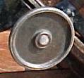
Stanley #113 Type 1 Adjustment Wheel
Sources: 1. Walter, John . "Antique &
Collectable Stanley Tools, Guide to Identity and Value", 2nd Edition, 1996
2. The Stanley Catalog Collection, 1855 to 1898, The Astragal Press, Mendham, New Jersey
3. Smith, Roger K., Reprint of Stanley Catalog No 120 orginally issued in 1923,
"Carpenters' and Mechanics Tools", The Stanley Rule and & Level Plant, The
Stanley Works, New Britain, Conn., U.S.A.
4. Wood, Jack P. "Early 20th Century Stanley Tools, Price Guide". Contains
reprints of the 1909 and 1926 Stanley Works Tool Catalogs.
5. Stanley #113 Type 1 in the personnel tool collection of Gordon Muster. Purchased for
$111 on Ebay in March,2001.
6. Past Ebay Listing
Stanley #113 Circular Plane Type 46